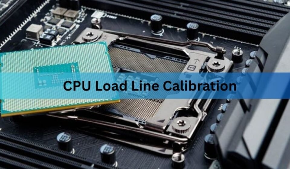

CPU load line calibration (LLC) is a motherboard setting that decides how much your CPU voltage is allowed to sag when the chip jumps from idle to full load. Set it higher and the voltage stays flatter under load. Set it lower and the voltage drops more, which is what the CPU was designed to expect. For most people the right answer is a middle setting, or leaving it on auto entirely.
The setting matters because voltage never sits still. It dips when work arrives and spikes when work stops. LLC changes the size of both. Get greedy with it and you trade a small stability win for voltage spikes that software will not show you.
What does load line calibration actually do?
LLC sets the slope of the voltage drop between idle and load. That slope is measured in milliohms, and the maths behind it is plain Ohm’s law: the drop equals the load line value multiplied by the current your CPU pulls.
An example makes it concrete. With a load line of 1 milliohm and a CPU drawing 100 amps, the voltage falls by 0.1 V. So 1.300 V set in BIOS arrives at the socket as 1.200 V under that load. Raise LLC and you shrink the gap. Push it to the top setting and the board tries to hold 1.300 V no matter what the current does.
The name is a poor fit. Nothing is being calibrated in the usual sense. You are picking how steep the droop line is, and the word “calibration” is left over from marketing rather than engineering.
Two numbers describe the result. Vdrop is the small difference between what you set and what the board actually delivers at idle. Vdroop is the larger difference between idle voltage and loaded voltage. LLC works on the second one.
The current figure is what makes this matter more now than it used to. A mid-range chip in a light workload might pull 40 amps, where the droop from a 1 milliohm load line is a harmless 0.04 V. The same chip running an all-core render can pull past 200 amps, and that identical load line now costs you 0.2 V. This is why droop feels invisible during browsing and suddenly causes crashes during video encoding or compiling. Nothing changed except the current.
Why does voltage drop under load in the first place?
That drop, called Vdroop, is deliberate. It is a design feature, not a fault your motherboard is failing to correct.
Here is why it exists. When a heavy load stops suddenly, the power stage keeps pushing current for a fraction of a second because it cannot react instantly. The stored energy in the inductors has to go somewhere, and it lands on the voltage rail as a spike called overshoot. If the resting voltage was already sitting low thanks to droop, that spike has empty space to rise into before it reaches the CPU’s ceiling.
Remove the droop and you remove the headroom. The spike now starts from a higher base and finishes higher. Chip makers publish limits for how high overshoot may go and for how long, and board makers have to design inside those limits. Droop is one of the main tools they use to stay inside them.
The reverse happens at the other end of the transition. When load arrives suddenly, voltage undershoots below the steady level for a moment before the VRM catches up. If that dip goes below what the cores need at their current speed, you get a crash. This is the real problem LLC was built to address, and it is worth keeping the two events separate in your head: undershoot causes crashes, overshoot causes wear.
What do the LLC levels mean on my board?
Every brand names them differently, and the numbering runs in opposite directions depending on who made your board. This is the single biggest source of confusion for people setting it for the first time.
| Brand | What it is called in BIOS | Range | Most aggressive |
|---|---|---|---|
| ASUS | CPU Load-line Calibration | Level 1 to Level 8 | Level 1 |
| ASRock | CPU Load-Line Calibration | Level 1 to Level 5 | Level 1 |
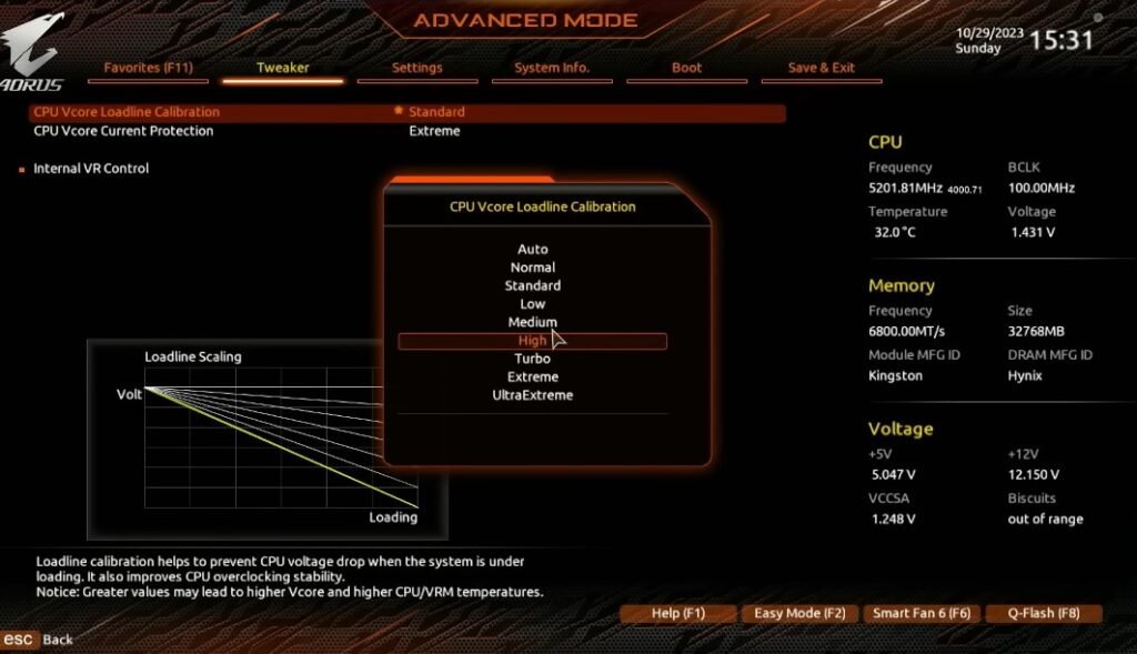
| Gigabyte | CPU Vcore Loadline Calibration | Standard to Ultra Extreme | Ultra Extreme |
| MSI | CPU Loadline Calibration Control | Mode 1 to Mode 8 | Mode 1 |
Read that table twice before changing anything. Level 1 on an ASUS board and Mode 1 on an MSI board both mean maximum compensation, while Gigabyte drops numbers altogether in favour of words. Copying an LLC number from a guide written for another brand is how people accidentally set the most aggressive option while believing they picked the mildest.
The levels are also not standardised in strength. Level 4 on one ASUS board may not deliver the same milliohm value as Level 4 on another ASUS board, because the profiles are tuned per model to suit the VRM fitted to it. Treat the numbers as relative positions within your own board’s range, nothing more.
What LLC setting should I use?
Start in the middle of your board’s range and only move from there if your own testing tells you to. On an ASUS board with eight levels, that means somewhere around Level 3 to Level 5. On MSI, Mode 4 to Mode 6. On Gigabyte, Medium or High rather than Turbo or Extreme.
Oscilloscope measurements taken directly from CPU die sense pins show why the middle works best. Under a load step of roughly 70 amps, moving past about level 3 flattened the voltage line but did not meaningfully improve the lowest voltage the CPU actually saw at the start of the transient. Meanwhile the overshoot after the load released kept growing. You pay in spikes, power draw, and heat for a benefit that has already stopped arriving. The full set of captures is worth a look in the ElmorLabs load-line measurements if you want to see the waveforms for yourself.
That gives you a simple rule. Raise LLC only until the minimum voltage under load stops sagging into crash territory. Past that point you are buying overshoot for nothing.
There is a second reason to stay off the extremes. The highest settings on many boards deliberately overshoot the target, delivering more voltage under load than you asked for. That behaviour exists for extreme overclockers running sub-zero cooling with power saving features switched off. It has no place in a machine that idles at your desk all day.
It also helps to know what LLC cannot do. It reacts to load, so it always responds slightly after the fact. The very first microseconds of a load step are handled by the capacitors around the socket, not by the control loop, which means the deepest part of an undershoot is largely fixed by your board’s hardware. No LLC level rescues that first dip. What LLC controls is the steady voltage that follows, and the size of the spike when the load lets go.
If crashes continue at a sensible LLC level, the answer is usually somewhere else: more Vcore, a slightly lower clock, or a lighter undervolt. Climbing the LLC ladder in search of stability tends to produce a system that survives the stress test and then crashes on the desktop, because the idle voltage crept up while the loaded voltage stayed the same.
How do I set and test load line calibration?
Work through these in order, and change one thing at a time. If you adjust LLC and Vcore together, you will not know which one fixed or broke your system.

- Record your current numbers. Install HWiNFO, open sensors-only mode, and note Vcore at idle and during a five minute all-core load. The difference between those two figures is your existing droop, and it is your baseline.
- Find the setting in BIOS. On ASUS boards it lives under Digi+ VRM. MSI calls it CPU Loadline Calibration Control, Gigabyte uses CPU Vcore Loadline Calibration, usually inside the advanced voltage or VRM menu.
- Pick the middle level and save. Leave every other voltage setting exactly where it was.
- Retest with logging switched on. Run the same workload and watch the minimum and maximum Vcore columns in HWiNFO rather than the live value. The peaks are the numbers that matter, and the live reading updates too slowly to catch them.
- Check your maximum. If peak Vcore is now climbing above the figure you set in BIOS, LLC is too aggressive for this board. Step down one level and test again.
- Test stability properly. Thirty minutes of a mixed load such as OCCT or Prime95 small FFTs, then several hours of whatever you actually do. Crashes on the desktop or at idle point to a problem at low load, not high load, so do not respond to those by raising LLC further.
- Watch temperature and power. Flatter voltage under load means more sustained power going into the chip. If package temperature climbed more than a few degrees, the setting is costing more than it returns.
| Log the maximum, not the average. A board sitting at a comfortable 1.25 V average can still be touching 1.40 V on every load release. Only the max column will show you that. |
One more test is worth running. Load your CPU hard, then stop the test abruptly and watch the max Vcore recorded in that moment. Load release is when overshoot happens, so a sudden stop tells you more about your LLC setting than any amount of steady stress testing. Sensor logging in HWiNFO captures this cleanly if you export the run to CSV.
Does load line calibration damage your CPU?
Moderate LLC does not damage anything. The top settings can, over a long period, and the damage is slow rather than sudden.
The mechanism is voltage overshoot rather than the steady voltage you see reported. Sustained high voltage degrades silicon gradually. It shows up as a chip that needs a little more voltage each month to stay stable at the same clock speed, until settings that ran fine last year start throwing errors.
Intel’s 13th and 14th generation desktop instability made this pattern very visible. High operating voltage was identified as the cause, with affected processors requesting above 1.55 V, and microcode updates released in 2024 capped those requests as a preventative measure. Chips already degraded were not recoverable by a patch. Aggressive LLC pushes voltage in exactly the same direction as that fault, which is a good argument for restraint even on a healthy system.
Your VRM shares the load too. Holding voltage flat through a 200 amp swing makes the power stages switch harder and run hotter. On a well-built board with a heavy heatsink that is fine. On a budget board with small MOSFETs and thin cooling, VRM temperature becomes the limiting factor before CPU stability does.
There is an efficiency cost as well, and it is easy to miss. Power rises with the square of voltage, so holding an extra 0.05 V under a heavy load does not add a rounding error to your power draw. It adds real watts, which your cooler then has to move. On a chip already bumping into its thermal limit, that extra heat can cost you boost clocks. The setting meant to make the system faster ends up making it slower.
Signs of a chip that has degraded are worth recognising early: settings that were rock solid six months ago now fail, crashes appear in one specific application before they spread, or you find yourself adding voltage every few weeks to hold the same clock. That pattern is a warning, and the correct response is to reduce voltage and LLC rather than add more.
Do I need to touch LLC if I am not overclocking?
No. At stock settings the default droop is part of the specification, and your board’s auto profile already matches it. Leave it alone.

Two situations are worth an exception. If you undervolt using a fixed Vcore, a slightly firmer LLC can stop voltage sagging too low during all-core work, since a low undervolt plus heavy droop is a common cause of crashes that only appear in rendering or compiling. And if a stable overclock is one small step out of reach, one level of LLC is gentler than adding 30 mV that your CPU then carries through every idle hour of the day.
On recent Intel platforms the picture has an extra layer. The VRM load line you choose has to agree with the AC load line value the processor uses to calculate how much voltage to request. If the two disagree, the CPU either asks for more voltage than it needs or too little to stay stable, and the symptoms look identical to a bad LLC choice. Change one and check the other.
AMD Ryzen systems using Precision Boost Overdrive and Curve Optimizer are simpler. The chip manages its own voltage curve continuously, so auto is usually correct, and a firm LLC just fights the algorithm. LLC becomes relevant again only if you set a fixed manual voltage, which most Ryzen owners have no reason to do.
Frequently asked questions
What LLC level is safest for daily use?
The middle of your board’s range. On ASUS that is roughly Level 3 to Level 5, on MSI Mode 4 to Mode 6. These hold voltage steadily enough under load without creating the large overshoot spikes that appear at the top levels.
Does higher LLC increase CPU temperature?
Yes, usually by a few degrees. Flatter voltage under load means more power delivered to the chip and more heat in both the CPU and the motherboard VRM. If temperatures jump sharply after a change, step the level back down.
Why is my Vcore higher than what I set in BIOS?
Your LLC is set too aggressively. At high levels the VRM overcorrects during load changes and pushes voltage above your set point. Drop one level and recheck the maximum Vcore value in HWiNFO.
Should I use LLC when undervolting?
Sometimes. A slightly firmer LLC stops an undervolted chip from drooping into crash territory during all-core work. Start one level above auto, test properly, and stop as soon as the system is stable.
Is LLC needed on AMD Ryzen with PBO enabled?
Usually not. PBO and Curve Optimizer manage voltage themselves, so auto is the better choice. LLC matters on Ryzen mainly when you set a fixed manual voltage instead.
Conclusion
Pick a middle LLC level, confirm it with HWiNFO logging, and stop there. What you want is the smallest amount of compensation that keeps your minimum voltage out of crash territory, with a maximum that never climbs above the figure you set in BIOS. If you run at stock speeds, leave the setting on auto and spend your time elsewhere. Extra levels buy very little stability and charge you in voltage spikes, heat, and a slow tax on the life of your chip.